A drip system fails when a buyer selects pipe by diameter or advertised litres per hour alone. You need to match emitter performance, hydraulic capacity, filtration, pressure control, installation hardware, and manufacturing quality to the field layout. By the end, you will have a practical specification for comparing suppliers and sizing a workable system.
Key takeaways
- Specify diameter, wall thickness, pressure rating, emitter spacing, and maximum lateral length.
- Match emitter flow and spacing to soil, crop, slope, and available operating pressure.
- Verify inlet-to-end pressure and discharge uniformity with field measurements.
- Require filtration, flushing, fertigation, valves, and compatible connectors in the system design.
What requirements should you put in a drip irrigation pipe specification?
Your RFQ must require these drip irrigation pipe requirements before you compare quotations: nominal internal diameter, minimum wall thickness, emitter spacing, emitter discharge, operating-pressure range, pressure rating, maximum lateral length, and whether the emitter is pressure-compensating or non-pressure-compensating.
A diameter without reference to wall series is incomplete; a flow rate without reference pressure and spacing is equally misleading.
| Product type | What to specify | Main risk |
|---|---|---|
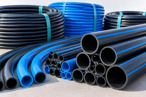
| Pressure pipe | Dimension ratio, pressure rating, temperature derating, joint method | Treating 20°C pressure as the hot-weather limit |
| Thin-wall emitting tube | Minimum wall thickness, emitter spacing, outlet geometry, coil length | Average thickness hiding weak sections |
| Non-pressure conveyance pipe | Internal diameter, wall series, bend radius, joining method | Using it where sustained pressure is required |
Ask irrigation pipe manufacturers for requirements covering UV stabilisation, polyethylene grade, permitted recycled content, resin-batch and production-lot traceability, and retained samples. Require dimensional inspection for ovality, emitter placement, weld integrity and minimum—not merely average—wall thickness.
Reference ISO 9261 for emitter and emitting-pipe specifications and test methods. Request test evidence for the applicable edition, including hydraulic results at more than one pressure; reject a general “ISO compliant” claim without records.
Your RFQ must also state minimum bend radius, allowable pull-in force, installation temperature, chemical compatibility, coil length, joint method and pressure-test procedure. Require the supplier to explain pressure rating against service life, resin classification, dimension ratio or wall-thickness series, and temperature derating.
How do you choose emitter flow rate, spacing, and lateral length?
Choose the emitter rate only after fixing crop type, plant spacing, row length, slope, inlet pressure, soil infiltration, and the number of emitters operating simultaneously. These inputs determine application intensity, pressure loss, and whether the drip pipe flow rates suit the irrigation zone.
Confirm what the quoted rate measures. At the manufacturer’s stated reference pressure, such as 1.0 bar, 1, 2, 4, or 8 L/h may mean:
| Basis | What the rate means | Example |
|---|---|---|
| Per emitter | Discharge from one emitter | 2 L/h at 1.0 bar |
| Per metre | Combined discharge assigned to each metre of pipe | 4 L/h per metre |
| Complete pipe | Total flow through one lateral | 500 L/h for a 100 m lateral |
Calculate emitter count as lateral length divided by spacing. Calculate lateral flow as emitter discharge multiplied by emitter count. Thus, 2 L/h emitters at 0.40 m spacing give 250 emitters on 100 m, producing 500 L/h, or 8.33 L/min.
Closer spacing with lower discharge spreads water more finely but increases emitter count and filtration demand. Wider spacing with higher discharge reduces emitter count but raises lateral flow and pressure loss.
A published maximum lateral length is not universal. It depends on internal diameter, emitter flow, spacing, terrain, inlet pressure, allowable pressure variation, and end pressure; request those assumptions.
Pressure-compensating emitters hold discharge more consistently across pressure changes. Non-pressure-compensating emitters follow pressure, so slope and friction alter flow. Include these drip irrigation pipe requirements in the design record.
How can you verify pressure and flow uniformity from inlet to end?
For a non-pressure-compensating emitter, discharge follows q = kPˣ. The exponent x is often near 0.5 for an orifice-controlled emitter, so doubling pressure does not normally double discharge. Flow uniformity therefore depends on pressure variation along the lateral as well as emitter manufacturing variation.
1. Flush the lateral and operate the zone at its normal design flow and pressure. Measure pressure at the inlet, midpoint, and end while water is flowing; a static pressure reading hides losses through the pipe and emitters.
2. At each pressure point, collect water from representative emitters with a graduated container for a timed interval. Sample enough emitters to represent the run, and record the emitter position, sample count, temperature, average discharge, lowest discharge, and highest discharge.
3. Calculate the coefficient of variation, or use the supplier’s stated equivalent uniformity metric. Compare the result with the acceptance limit in your specification, not with a catalogue claim alone.
An uphill lateral loses pressure as elevation rises; a downhill lateral gains pressure. An inlet regulator controls starting pressure but cannot remove the pressure change created by a long slope, so divide sloping blocks into pressure zones.
Keep laterals level where possible, avoid kinks, and provide workable end flushing. Ask irrigation pipe manufacturers for requirements behind the published length table, including test pressure, acceptable pressure variation, end-of-line pressure, and the terrain assumptions used. Record these alongside drip pipe flow rates during field acceptance.
Which filters, valves, connectors, and fertigation parts must the system include?
A filter must protect the emitter’s smallest flow passage, not merely match a mesh number. Specify a nominal or absolute micron rating and compare it with the actual contaminant load; mesh counts alone do not identify opening size.
| Contaminant | Required response |
|---|---|
| Suspended sand and silt | Sediment separator, screen or disc filter, and regular flushing |
| Iron deposits | Oxidation and media treatment before final filtration |
| Algae or biological growth | Chlorination under controlled dosing and more frequent cleaning |
| Hardness scale | Acid management under agronomic control, followed by flushing |
These drip irrigation pipe requirements also include the filter’s clean and dirty differential-pressure limits, flow capacity, flushing method, and maintenance interval. Obtain each value from the supplier. Without a workable end flush manifold or removable end line, sediment and growth collect at lateral ends.
Build the hydraulic train in this order:
- Pump, mainline, submain, zone valve, pressure regulator, and pressure gauges
- Air-release and vacuum-relief valves at high points
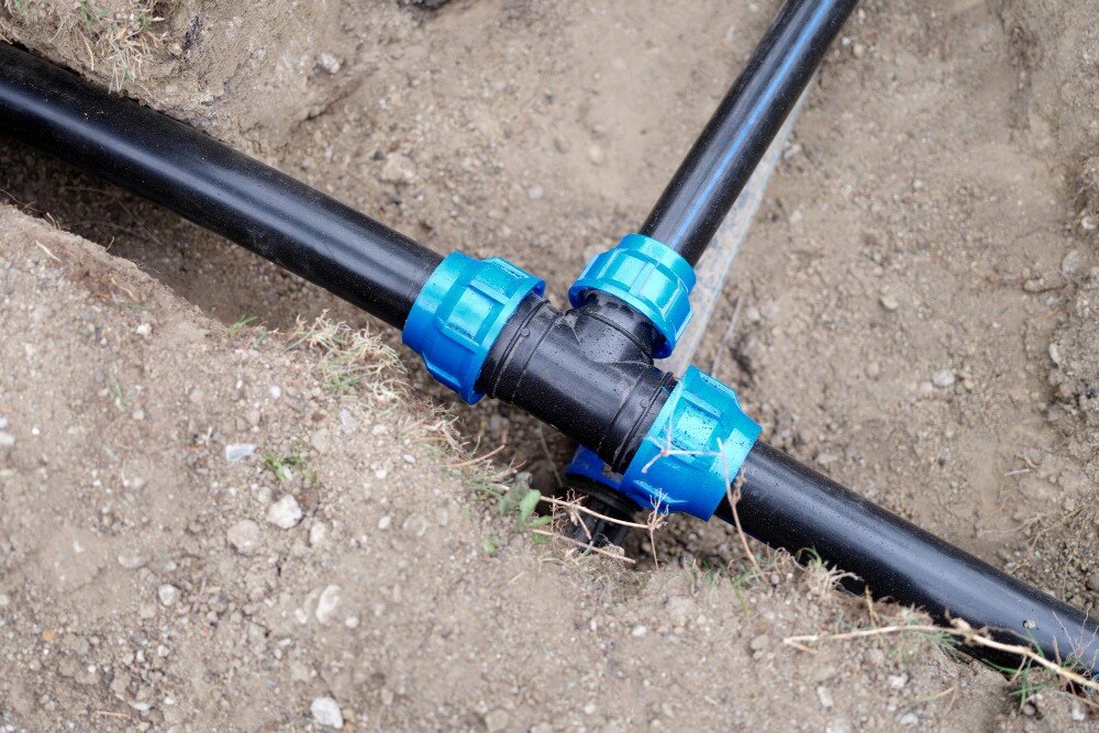
- Take-off connectors, grommets, end caps, and flush manifolds
- Dosing or injection unit, non-return valve, isolation valves, calibration record, and post-injection clean-water flush
Size the pump from emitter discharge multiplied by simultaneous emitter count, then add capacity for active zones, filtration losses, elevation, and required operating hours. For example, 2 L/h emitters at 0.40 m spacing give 250 emitters per 100 m, or 500 L/h (8.33 L/min). Drip pipe flow rates without spacing and pressure are incomplete.
How should you evaluate drip pipe manufacturing and an irrigation pipe manufacturer in Pune?
Approve a drip line only after the supplier proves both material control and hydraulic performance. A polished coil can still contain thin sections, misplaced emitters, or flow drift that field installation will expose.
1. Ask for the polyethylene grade, melt-flow or processing-control limits, UV-stabilisation approach, permitted recycled content, resin-batch traceability, production-lot identification, retained samples, and calibrated equipment records.
2. Require dimensional inspection for minimum wall thickness, internal diameter, ovality, emitter spacing, outlet geometry, coil length, and emitter placement. Record the results by production lot.
3. Require hydraulic samples at more than one pressure. The quality file must show pressure-flow results, flow uniformity or coefficient of variation, pressure-test basis, temperature derating, flushing guidance, and test evidence for the applicable edition of ISO 9261.
4. Request filtration assumptions, maximum-lateral calculations, installation limits, and warranty conditions. The published lateral length is valid only against stated internal diameter, discharge, spacing, inlet pressure, slope, allowable pressure variation, and end pressure.
5. Use the same checklist for an irrigation pipe manufacturer in Pune. Location does not prove emitter performance, and a company making HDPE ducts or other plastic products must demonstrate irrigation-specific testing and documented drip pipe manufacturing controls.
Before approving Harsh Agro Pipes And Fittings, request this complete batch and test file rather than accepting a catalogue claim. These are practical requirements for comparing irrigation pipe manufacturers: assess discharge, spacing, lateral length, filtration burden, and installed cost together, because improving one can increase another.
Frequently asked questions
What requirements should you put in a drip irrigation pipe specification?
State nominal internal diameter, minimum wall thickness, emitter spacing, emitter discharge, operating-pressure range, pressure rating, maximum lateral length, and whether emitters are pressure-compensating. Also specify material, coil length, connection type, test method, and required certificates.
How do you choose emitter flow rate, spacing, and lateral length?
Choose emitter flow and spacing from crop water demand, soil texture, root-zone width, row spacing, slope, and irrigation frequency. Use the manufacturer’s hydraulic tables to set lateral length so pressure loss stays within the permitted range.
How can you verify pressure and flow uniformity from inlet to end?
Measure pressure at the lateral inlet, midpoint, and tail while the system operates. Collect discharge from emitters at those points, compare the readings, and investigate clogged filters, undersized pipes, excessive length, elevation change, or incorrect pressure.
Which filters, valves, connectors, and fertigation parts must the system include?
Specify a screen or disc filter with a stated mesh rating and flow capacity, pressure gauges, isolation and flush valves, air-release valves, take-off connectors, end closures, and a non-return valve, injection point, and backflow protection for fertigation.
How should you evaluate drip pipe manufacturing and an irrigation pipe manufacturer in Pune?
Ask for production drawings, resin grade, wall-thickness controls, emitter spacing tolerances, pressure and discharge test records, batch traceability, sample coils, warranty terms, and hydraulic design support. Compare the evidence against your field conditions, not only the quoted price.
Keywords